I do think the Goldpoints are neater as well.
Ben -
Since you're using 24V relays and have a +/-15 supply all you have to do is connect the relay common to -15V and the unregulated relay supply to +15.
The differential is 30V and the relay regulator only has to drop 6V.
It shouldn't be a thermal issue given the heatsink size.
Do note that the relay and control switch common will be at -15V and the relay regulated supply, when measured to ground, will appear to be +9V. (-15V +24V = +9V.)
If you wanted to leave yourself some room to grow use a +/-15V supply for the audio and a separate 24V supply for the relays.
The on-board regulators won't be required.
For each board requiring +/-15V I would devise a power distribution block near the power supply output (or connector) and take the +/-15V and DC 0V return lines from each board back to it.
I certainly wouldn't daisy-chain it from one board to the next.
Make the audio DC lines and relay supply lines "home runs" to the distribution block.
MTC-IGFO Mastering Transfer Console Input Gain Filter Output Construction Information
-
mediatechnology

- Posts: 5466
- Joined: Sat Aug 11, 2007 2:34 pm
- Location: Oak Cliff, Texas
- Contact:
Re: MTC-IGFO Transfer Console Input Gain Filter Output Construction Information
I like Phoenix UT 2.5 DIN rail blocks.You can see them in the pictures of stuff I've built.mediatechnology wrote: ↑Thu May 31, 2018 9:54 am For each board requiring +/-15V I would devise a power distribution block near the power supply output (or connector) and take the +/-15V and DC 0V return lines from each board back to it.
I certainly wouldn't daisy-chain it from one board to the next.
Make the audio DC lines and relay supply lines "home runs" to the distribution block.
https://www.mouser.com/ProductDetail/651-3044076
-
mediatechnology
- Posts: 5466
- Joined: Sat Aug 11, 2007 2:34 pm
- Location: Oak Cliff, Texas
- Contact:
Re: MTC-IGFO Transfer Console Input Gain Filter Output Construction Information
Thanks Paul. Roger used to use those.
I've also used barrier strips with the links that jumper between sections for that as well.
BTW Surplus Sales of Nebraska is very cool. https://www.surplussales.com/Electrical ... rip-1.html
I've also used barrier strips with the links that jumper between sections for that as well.
BTW Surplus Sales of Nebraska is very cool. https://www.surplussales.com/Electrical ... rip-1.html
Re: MTC-IGFO Transfer Console Input Gain Filter Output Construction Information
That model of block can take 12 ga - 26 ga wire. They can be used for all the different wiring I deal with. I use them for DC power distribution mostly but I have used them for AC power distribution in racks and also for audio signal distribution occasionally.
Re: MTC-IGFO Transfer Console Input Gain Filter Output Construction Information
Thanks for the heads up. As I am still awaiting parts, I will have to keep this in mind when assembling later and testing. Duly noted on the Goldpoints for future reference!Gold wrote: ↑Thu May 31, 2018 9:18 am Elma 04’s are very sensitive to overheating. If you end upbwith a noisy switch it’s damaged beyond repair. I’ve destroyed my share. It’s an expensive lesson. I think it’s worth the money to buy an unstuffed Goldpoimt if the potentiometer configuration works for the application.
Excellent. Thank you so much for the thorough explanation, this is an immense help and makes much more sense now!mediatechnology wrote: ↑Thu May 31, 2018 9:54 am Since you're using 24V relays and have a +/-15 supply all you have to do is connect the relay common to -15V and the unregulated relay supply to +15.
The differential is 30V and the relay regulator only has to drop 6V.
It shouldn't be a thermal issue given the heatsink size.
Do note that the relay and control switch common will be at -15V and the relay regulated supply, when measured to ground, will appear to be +9V. (-15V +24V = +9V.)
If you wanted to leave yourself some room to grow use a +/-15V supply for the audio and a separate 24V supply for the relays.
The on-board regulators won't be required.
For each board requiring +/-15V I would devise a power distribution block near the power supply output (or connector) and take the +/-15V and DC 0V return lines from each board back to it.
I certainly wouldn't daisy-chain it from one board to the next.
Make the audio DC lines and relay supply lines "home runs" to the distribution block.
Thank you for the recommendation! I'll be looking into using these and placing (yet) another order soon.Gold wrote: ↑Thu May 31, 2018 10:56 amI like Phoenix UT 2.5 DIN rail blocks.You can see them in the pictures of stuff I've built.mediatechnology wrote: ↑Thu May 31, 2018 9:54 am For each board requiring +/-15V I would devise a power distribution block near the power supply output (or connector) and take the +/-15V and DC 0V return lines from each board back to it.
I certainly wouldn't daisy-chain it from one board to the next.
Make the audio DC lines and relay supply lines "home runs" to the distribution block.
https://www.mouser.com/ProductDetail/651-3044076
Best
Brian
-
mediatechnology
- Posts: 5466
- Joined: Sat Aug 11, 2007 2:34 pm
- Location: Oak Cliff, Texas
- Contact:
Re: MTC-IGFO Mastering Transfer Console Input Gain Filter Output Construction Information
Update August 20, 2020: MTC-IGFO Assembly, Schematics and Test Instructions: https://www.ka-electronics.com/images/p ... 2020_1.pdf
Minor corrections to the assembly text.
Minor corrections to the assembly text.
-
mediatechnology
- Posts: 5466
- Joined: Sat Aug 11, 2007 2:34 pm
- Location: Oak Cliff, Texas
- Contact:
Re: MTC-IGFO Mastering Transfer Console Input Gain Filter Output Construction Information
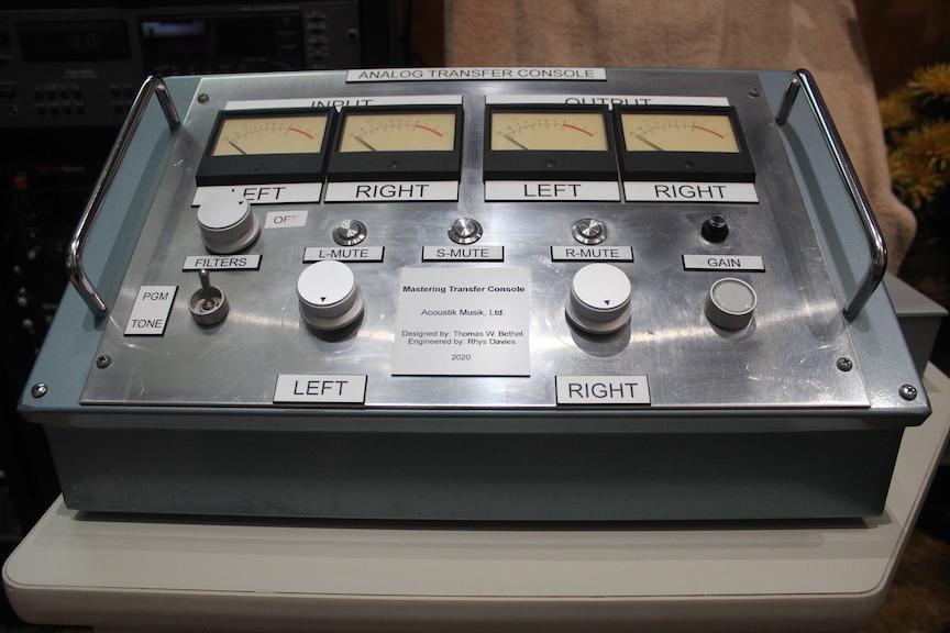
"Got our mastering transfer console finished"
Thanks for the shout out Thomas!Thomas W. Bethel
We have been working on this for the past two and a half years and it is finally finished. My tech wiz, Rhys Davies, built the whole unit himself and wired it. We had lot of changes along the way but it works GREAT and we got exactly what we wanted. S/N -95.5 dBM, Distortion .0005%, Frequency Response 20 t0 20 KHz +/- .5 dB. It is built in an old "industrial control unit" shell that we got from the surplus store. It is built using the MTC board from here https://www.ka-electronics.com/shop/. I am very proud of Rhys, he is a junior at Ohio Northern University studying electronic engineering and has worked here for 4.5 years as an intern.
https://recording.org/forum/mastering/g ... e-finished
Re: MTC-IGFO Mastering Transfer Console Input Gain Filter Output Construction Information
Nice!
Best,
Doug Williams
Electromagnetic Radiation Recorders
Doug Williams
Electromagnetic Radiation Recorders
-
Bespoke Electronics
- Posts: 3
- Joined: Tue Feb 14, 2023 10:50 pm
Re: MTC-IGFO Mastering Transfer Console Input Gain Filter Output Construction Information
I went through and updated the Gain Switch BOM. All but one value is KOA Speer now.
-
mediatechnology
- Posts: 5466
- Joined: Sat Aug 11, 2007 2:34 pm
- Location: Oak Cliff, Texas
- Contact:
Re: MTC-IGFO Mastering Transfer Console Input Gain Filter Output Construction Information
Thank you for doing that.
On later projects I started using Yageo or KOA from Mouser but haven't gone back to update the old discontinued Xicon numbers.
Do you have a link to the updated BOM?
On later projects I started using Yageo or KOA from Mouser but haven't gone back to update the old discontinued Xicon numbers.
Do you have a link to the updated BOM?